
SBP‑800‑ATS
SBP-800-ATS Mobile Automatic Transfer Switch, 800 A
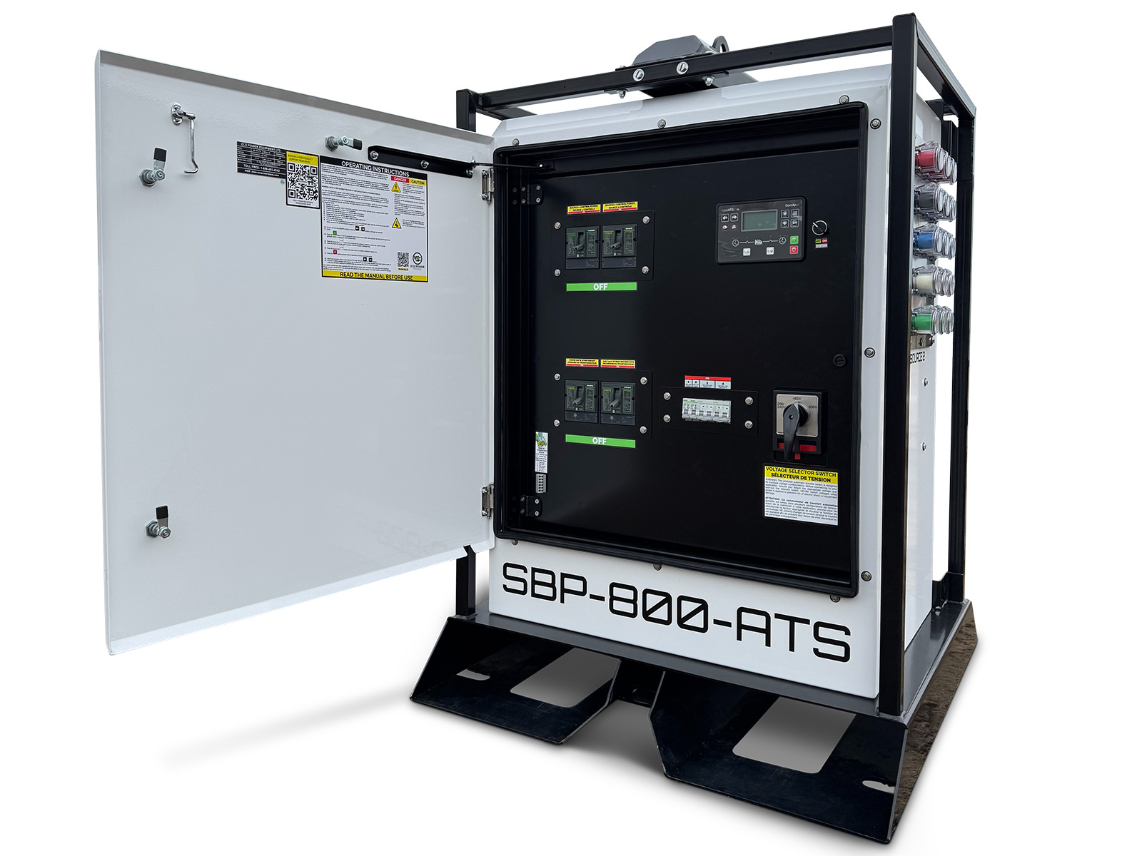
Features
- Heavy-duty contactor-based design
- Programmable amber beacon with high-visibility LED
- Switchable voltage design: 120/208 V, 120/240 V, 277/480 V, 347/600 V with lockable selector switch
- Integrated control-panel heating system, arctic-rated design
- Advanced control system for application flexibility
- Amperage monitoring and data logging
- Fully programmable controller for application integration
- Display of all critical ATS measures
- Remote cellular or satellite telematics ready
- Integrated battery backup system with one-week life
- Battery charging port with battery disconnect
- Single-point lifting bail, engineered and rated
- Highly portable enclosure with fork pockets, castor ready
- Rugged base frame and enclosure for mobile applications
- Aluminum enclosure for long-term wear
- Lockable latches standard, key or external lock
- Stackable frame
- Simple access for maintenance and operations
- Camlock source and load connections on Eco Power standard cam panels, paralleled per phase
- Wide range of options and accessories available
Application notes
- Camlock connections are paralleled per phase so the unit holds full rating at high ambient: each 400 A cam is derated to 320 A in heat
- Contactor ratings are IEC utilization-category values at the switching device; ATS rating is 800 A
- Rated operating temperature -40 to +40 °C
- Integrated 25 kVA transformer feeds the shore power package
Unit specifications
| Ratings | |
|---|---|
| Rated current | 800 A |
| Phases | Three-phase (3Ø) |
| Maximum system voltage | 600 V AC |
| Selectable voltages |
Lockable selector switch. |
| Operating temperature | -40 to +40 °C (-40 to 104 °F) |
| Switching | |
| Switching device | Contactor |
| Device standards | CSA C22.2 No. 14, UL 60947-1, UL 60947-4-1, IEC 60947-1, IEC 60947-4-1 |
| Operating voltage window | 85% to 110% of nominal |
| Drop-off voltage window | 20% to 65% of nominal |
| Switching device ratings |
|
| Controls and protection | |
| Controller | ComAp |
| Controller features |
|
| Protections |
|
| Connections | |
| Camlock connections | 3 × 400 A per phase, paralleled |
| Installed cam capacity per phase | 1200 A nominal · 960 A at the 320 A/cam high-ambient derate |
| Shore power | |
| Shore power package |
|
| Physical | |
| Weight | 1,194 lb |
| Enclosure type | NEMA 3R |
| Lifting | Single-point lifting bail, engineered and rated; fork pockets; castor ready |
| Compliance and approvals | |
| Standards | SPE-1000, CSA C22.2 No. 178.1, UL 1008 |
We work diligently to ensure all product information is accurate at the time of publication. Specifications, features, dimensions, and availability are subject to change without notice. Images are for illustration purposes and may show optional equipment or configurations that differ from the product supplied. Published information is provided for general reference and does not constitute a warranty or contractual commitment. Confirm all critical specifications and application requirements with us in writing before ordering. Final supply is governed by the accepted order and applicable terms of sale. To the extent permitted by law, we disclaim liability for errors, omissions, or reliance on outdated information. Nothing in this notice overrides expressly agreed contractual obligations or applicable statutory rights.